
Inverter Duty Transformers:
A Buyer's Guide to Selection, Specifications & Standards
If you are specifying a transformer for a solar power plant, wind energy project, or variable-frequency drive application, a standard distribution transformer is not sufficient. You need an inverter duty transformer — a unit specifically engineered to handle the non-linear, high-frequency switching signals that inverters produce.
This guide is written for procurement engineers, EPC project managers, and technical buyers who need to move beyond brochure-level information and understand exactly what to specify, why it matters, and what can go wrong when the wrong transformer is selected.
KLR Transformers manufactures inverter duty units from 25 kVA to 20 MVA+, custom-engineered to IS 2026 and IEC 60076 standards.
Have a project specification? Contact our engineering team for a technical consultation and datasheet — no obligation.
1. What Makes an Inverter Duty Transformer Different?
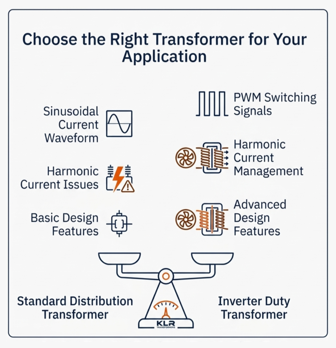
Standard distribution transformers are designed for sinusoidal current — clean, 50 Hz waveforms from the grid. Inverters do not produce sinusoidal current. They use pulse-width modulation (PWM) switching, typically at frequencies between 2 kHz and 20 kHz, to synthesise an AC output from a DC source.
This switching behaviour introduces harmonic currents — primarily the 5th, 7th, 11th, and 13th harmonics — into the transformer windings. In a standard transformer, these harmonics cause:
- Elevated eddy current losses in the core and windings
- Dielectric stress on insulation materials
- Hotspot temperatures that significantly shorten transformer life
- Audible noise and vibration beyond normal operating levels
An inverter duty transformer is specifically designed to manage these effects. The key design differences include reinforced winding geometry, increased conductor cross-section to handle harmonic-induced heating, electrostatic shielding between primary and secondary windings, and an elevated K-factor rating — explained in detail below.
2. Understanding the K-Factor Rating
The K-factor is the most important specification that distinguishes inverter duty transformers from standard units. It quantifies the ability of a transformer to handle harmonic currents without overheating.
A K-1 transformer is rated for purely sinusoidal loads — no harmonics. A standard utility distribution transformer is K-1.
A K-13 transformer can handle harmonic loading equivalent to 13 times the eddy current heating of a linear load — appropriate for most solar and industrial inverter applications.
As a general guideline for selection:
| Application | Typical K-Factor | Notes |
|---|---|---|
| Solar rooftop / small PV (< 100 kW) | K-4 | Mild harmonic environment |
| Utility-scale solar (100 kW – 10 MW) | K-7 to K-13 | Multiple inverter strings; parallel harmonic paths |
| Wind turbine step-up | K-7 to K-13 | Variable-speed turbine generators |
| VFD motor drives (industrial) | K-13 to K-20 | Heavy harmonic content from drive switching |
| Battery storage (BESS) systems | K-7 to K-13 | Bidirectional power flow; mixed harmonic profile |
KLR manufactures inverter duty transformers rated from K-4 to K-20. Our engineering team can calculate the correct K-factor for your specific inverter configuration — contact us with your single-line diagram and we will specify the right unit.
3. Key Technical Specifications to Include in Your RFQ
When raising a request for quotation (RFQ) for an inverter duty transformer, vague specifications result in generic quotes — and a transformer that may not survive the operating environment. The following parameters must be defined:
| Parameter | Standard Range | KLR Custom Range |
|---|---|---|
| Power Rating (kVA) | 25 kVA – 10 MVA | 25 kVA – 20 MVA+ |
| Voltage Class | Up to 33 kV | Up to 66 kV |
| Frequency | 50 Hz / 60 Hz | 50 Hz / 60 Hz |
| Cooling Type | ONAN / ONAF | ONAN / ONAF / OFAF |
| Harmonic K-Factor | K-4 to K-13 | K-4 to K-20 (custom) |
| Insulation Class | Class A / B / F | Class F / H (high-temp) |
| Applicable Standards | IS 2026 / IEC 60076 | IS 2026 / IEC 60076 / IEEE C57.110 |
| Electrostatic Shield | Optional | Standard on solar/wind units |
4. Applicable Standards: IS 2026 and IEC 60076
For projects in India, all transformer specifications should reference IS 2026 (Parts 1–5), which governs power transformer design, testing, and performance requirements. IS 2026 is harmonised with IEC 60076, the international standard for power transformers.
For inverter duty transformers specifically, the following standards and guidelines are relevant:
- IS 2026 / IEC 60076 — General requirements for power transformers
- IEC 61000-2-2 — Compatibility levels for harmonic voltages in public supply networks
- IEEE C57.110 — Recommended practice for establishing transformer capability when supplying non-sinusoidal load currents (K-factor methodology)
- IEC 62477-1 — Safety requirements for power electronic converter systems (relevant for inverter interface)
Buyers procuring from KLR receive test certificates issued in accordance with IS 2026 / IEC 60076 as standard. Type test reports, routine test reports, and special tests (including temperature rise tests and short-circuit withstand tests) are available on request.
5. Selection Criteria: A Practical Checklist for Buyers
Use the table below as a pre-specification checklist before issuing an RFQ or approaching a manufacturer:
| Selection Factor | What to Specify | Why It Matters |
|---|---|---|
| kVA Rating | Match inverter output + 15–20% derating margin | Prevents overheating under harmonic load |
| K-Factor Rating | K-4 for mild harmonics; K-13 or higher for heavy drives | Determines winding design for harmonic tolerance |
| Cooling Method | ONAN for standard; ONAF/OFAF for high-density sites | Site ambient temperature affects transformer life |
| Voltage Ratio | Confirm inverter AC output voltage vs. grid voltage | Mismatch causes protection relay trips |
| Electrostatic Shield | Mandatory for sensitive electronic loads downstream | Reduces conducted EMI from switching noise |
| Enclosure / IP Rating | IP54 minimum for outdoor solar/wind sites | Protects against dust and water ingress |
6. Common Specification Errors — and How to Avoid Them
In our experience working with solar EPC contractors and industrial projects across Andhra Pradesh and Telangana, the following are the most frequently encountered specification errors:
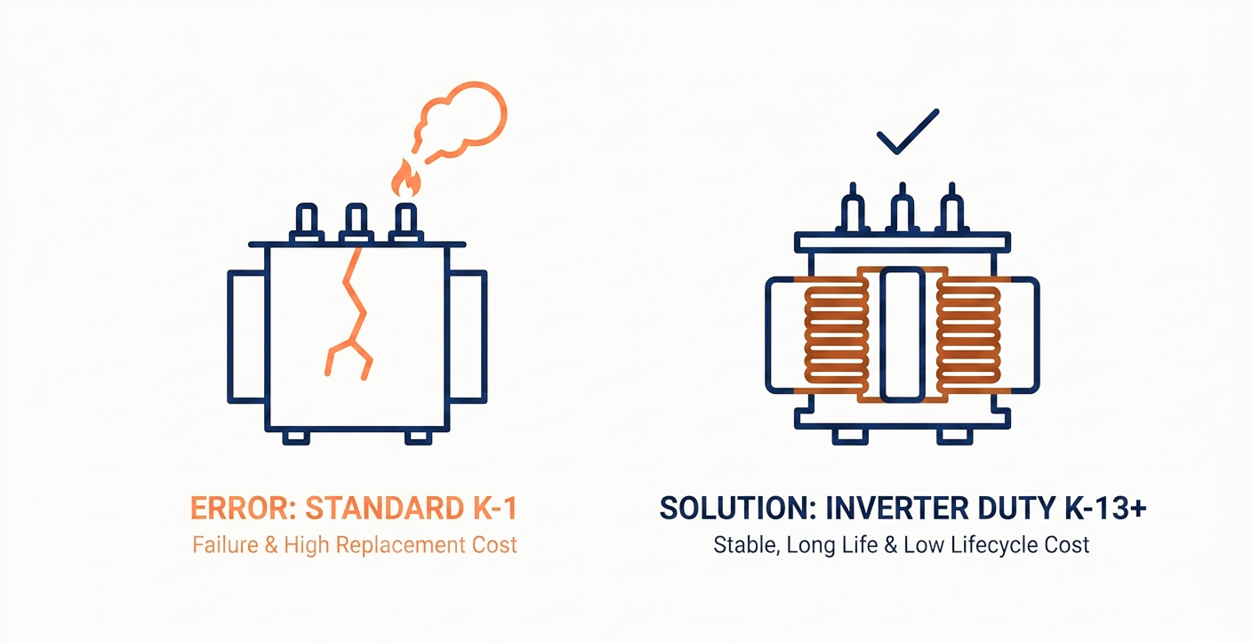
Specifying standard distribution transformer instead of inverter duty
The most costly error. A standard transformer used in an inverter-driven system will experience accelerated winding insulation degradation, reduced service life (sometimes from 25 years to under 5 years), and potential failure under peak harmonic loading. Replacing a failed transformer mid-project far exceeds the cost differential at procurement.
Undersizing kVA due to ignoring derating
Buyers often match transformer kVA rating directly to inverter output rating. The 15–25% derating requirement is frequently overlooked, particularly in budget-driven procurement. Specify to the derated value, not the nameplate value.
Omitting electrostatic shielding specification
Electrostatic shielding (a Faraday shield between primary and secondary windings) is critical when the load downstream includes sensitive electronics or control systems. It significantly reduces conducted EMI from inverter switching. Many buyers do not know to ask for it.
Ignoring ambient temperature and altitude
Transformer ratings assume a standard ambient of 40°C at sea level. For sites in high-temperature regions or elevations above 1,000 metres, uprated cooling or derating is required. In Visakhapatnam and coastal Andhra, high humidity and salt-laden air also require appropriate enclosure (IP) ratings and anti-corrosion treatments.
7. Applications: Where Inverter Duty Transformers Are Used
Inverter duty transformers are specified across a wide range of applications. KLR has supplied units for the following project types:
- Utility-scale solar power plants — step-up transformers connecting solar inverter output (typically 400V or 690V) to 11 kV or 33 kV grid feeders
- Wind energy projects — turbine step-up transformers handling variable-frequency generator output via full-power converters
- Industrial VFD installations — isolation and step-up transformers for variable-frequency drives on large motors in pumping stations, compressors, and conveyors
- Battery Energy Storage Systems (BESS) — bidirectional transformers for grid-connected storage applications
- EV charging infrastructure — step-down isolation transformers for DC fast-charging inverter systems
- Captive solar + industrial hybrid plants — combined solar-and-grid applications requiring transformers capable of handling mixed sinusoidal and non-sinusoidal loads simultaneously
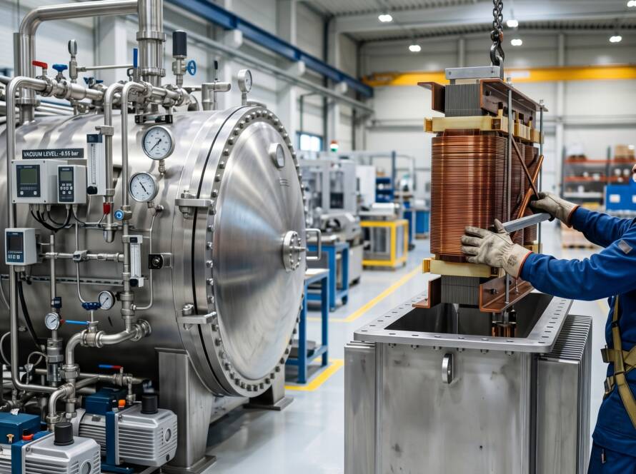
8. How KLR Engineers Inverter Duty Transformers
At KLR Transformers, inverter duty units are not adapted from standard designs — they are engineered from the winding specification upward for non-linear load conditions. Our design process includes:
- Harmonic current analysis based on the buyer's inverter type, switching frequency, and load profile
- K-factor calculation using IEEE C57.110 methodology to determine required conductor sizing and winding geometry
- Electrostatic shield design as standard on all solar and wind units
- Thermal modelling to verify hotspot temperatures under maximum harmonic loading conditions
- Factory acceptance testing (FAT) including routine tests per IS 2026 — ratio test, insulation resistance, induced overvoltage, no-load and load loss measurement
Our manufacturing facility in Visakhapatnam produces transformers for projects across South India, with units supplied to solar and industrial customers in Andhra Pradesh, Telangana, Tamil Nadu, and Karnataka. We also support export requirements for clients in the Gulf and Southeast Asia.
Ready to specify your inverter duty transformer?
Share your project details — inverter rating, site location, voltage class, and application type — and our engineering team will provide a technical specification and indicative pricing within 48 hours.
Email: enquiries@klrtransformers.com | Phone: [Your Number] | Web: [Your Website]
Frequently Asked Questions
A standard isolation transformer is designed for sinusoidal loads. An inverter duty transformer is designed for non-linear (harmonic-rich) loads produced by inverters. The key design differences are the K-factor rating, reinforced winding insulation, increased conductor cross-section, and electrostatic shielding. Using a standard isolation transformer in an inverter application will result in premature failure.
Start with your inverter's maximum AC output in kW. Convert to kVA using the power factor (typically 0.95–1.0 for solar inverters). Then apply a derating factor of 15–25% for harmonic loading. For example, a 500 kW inverter at unity power factor requires approximately 625–650 kVA nameplate rating minimum.
For a utility-scale solar plant in the 500 kW to 5 MW range with string or central inverters, K-7 to K-13 is the typical specification range. The exact value depends on the inverter type (string vs. central), total harmonic distortion (THD) output specification from the inverter manufacturer, and whether multiple inverters share a single transformer.
Yes. KLR manufactures to IEC 60076 standards, which are accepted in most international markets. We can also manufacture to specific national standards on request. Please contact our team with your project specifications and destination country.
Lead time depends on rating and specification. Standard units (25–500 kVA) are typically available in 4–6 weeks. Custom-engineered units above 1 MVA may require 8–12 weeks. Contact our team early in the project schedule to avoid delays.
Speak to a KLR Transformer Engineer
We work with EPC firms, solar developers, and industrial buyers to specify, manufacture, and deliver transformers built for the actual demands of your project — not the theoretical ones.
Request a Technical Consultation → enquiries@klrtransformers.com