
Power Transformer vs Distribution Transformer:
A Specification Guide for Industrial Buyers
Ask most electrical engineers what the difference is between a power transformer and a distribution transformer, and you will get a reasonable answer. Ask them which one to specify for a specific project — and the answer becomes more complex.
This guide is written for procurement managers, project engineers, and EPC teams who need to make that specification decision and understand its implications. It covers the technical differences, the applicable Indian and international standards, the lifecycle cost considerations that are rarely discussed in transformer literature, and a project-type reference table to help you identify the right transformer class for your application.
KLR Transformers manufactures both power transformers and distribution transformers. We have no commercial interest in steering you toward one type over the other — only in helping you specify the right one so it performs as required over its 25–30-year service life.
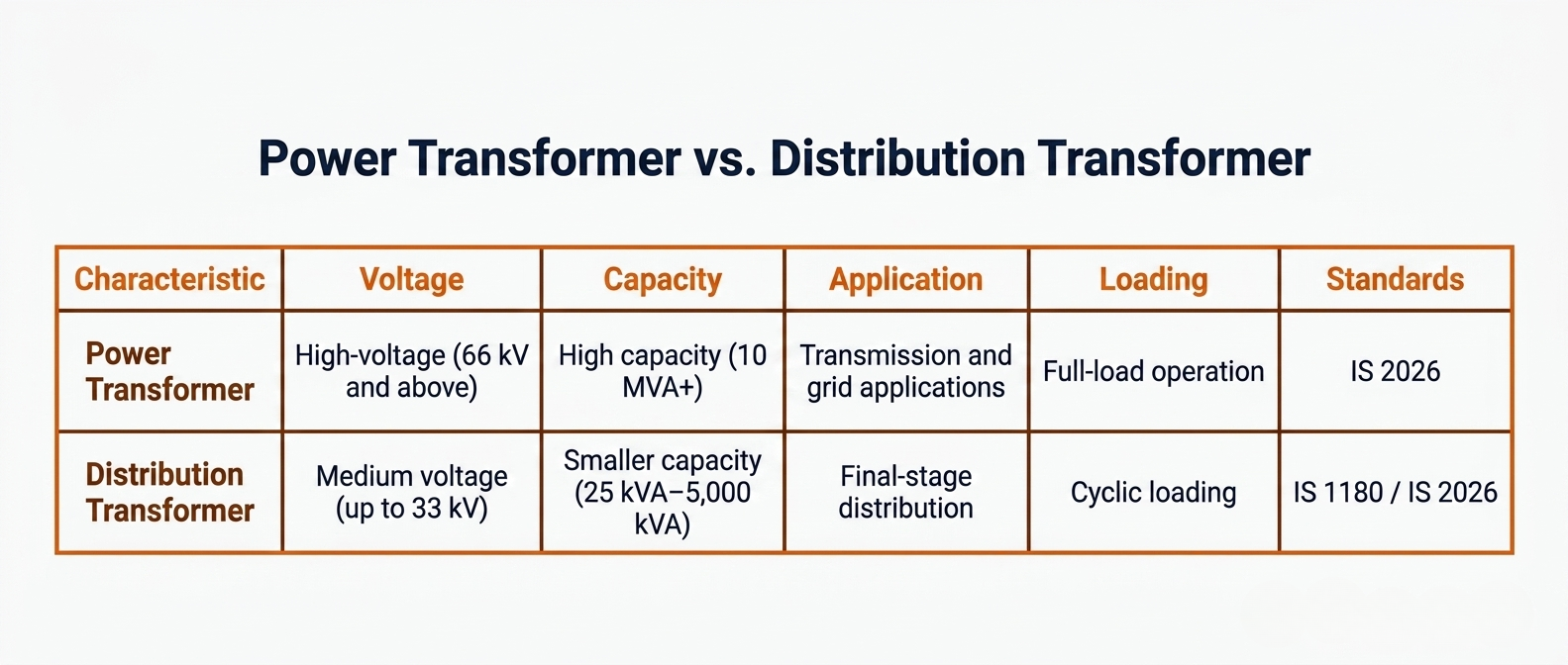
At a Glance
Power transformers: High-voltage (66 kV and above), high capacity (10 MVA+), transmission and grid applications, full-load operation, IS 2026.
Distribution transformers: Medium voltage (up to 33 kV), smaller capacity (25 kVA–5,000 kVA), final-stage distribution, cyclic loading, IS 1180 / IS 2026.
Both types are manufactured by KLR Transformers to IS 2026 / IEC 60076 standards. Contact us for a technical consultation on your project specification.
1. Core Definitions
Power Transformers
A power transformer is a transformer designed for bulk power transmission and grid interconnection at high and extra-high voltages. Power transformers are found at generating stations (stepping up generator output voltage for transmission), at grid substations (stepping down from transmission to sub-transmission voltage), and at the input of major industrial facilities receiving supply directly from the transmission network.
In India, power transformers typically operate at 66 kV, 110 kV, 132 kV, 220 kV, 400 kV, and 765 kV. Capacity ratings range from approximately 10 MVA at the lower end to over 1,000 MVA for large generating station step-up transformers.
A key characteristic of power transformers is that they are designed to operate at or near full load continuously. The design priority is minimising load (copper/I²R) losses at full load, since the transformer carries near-rated current throughout its operating cycle.
Distribution Transformers
A distribution transformer is a transformer that delivers power from the distribution network to the end user — a factory, a commercial building, a residential area, or a captive power consumer. Distribution transformers are the final transformer stage before power reaches a low-tension (LT) switchboard, motor control centre, or building main switch.
In India, distribution transformers typically step down from 11 kV, 22 kV, or 33 kV to 433V / 415V (three-phase) or 230V (single-phase). Capacity ratings standardised under IS 1180 include 25, 63, 100, 160, 200, 250, 315, 400, 500, 630, 800, 1,000, and 1,600 kVA. Larger distribution transformers up to 10 MVA are also manufactured to IS 2026 for industrial applications.
Unlike power transformers, distribution transformers are energised continuously — 24 hours a day, 365 days a year — but carry load that varies significantly across the day. The design priority therefore shifts: minimising no-load (core/iron) losses becomes critical, because these losses occur whether the transformer is supplying load or not.
2. Technical Comparison: Power vs. Distribution Transformers
| Parameter | Power Transformer | Distribution Transformer |
|---|---|---|
| Voltage class | Typically 66 kV, 110 kV, 220 kV, 400 kV and above | Typically 11 kV, 22 kV, 33 kV — stepping down to 415V / 433V LT supply |
| Rated capacity | From ~10 MVA to 1,000+ MVA | 25 kVA to 5,000 kVA (standard range); specialist units to 10 MVA |
| Primary application | Bulk power transmission — power plant step-up, grid interconnection, EHV substations | Final-stage distribution — industrial feeders, residential networks, captive power, renewable energy plant output |
| Load profile | Operates near full load continuously — designed for constant, steady load | Load varies significantly across the day; designed for cyclic and part-load operation |
| Efficiency priority | Optimised for load (copper) losses — full-load efficiency is paramount | Optimised for no-load (iron/core) losses — energised continuously regardless of load |
| Cooling type (IEC) | ONAN, ONAF, OFAF, ODWF — complex forced cooling systems for high heat output | ONAN standard for most ratings; ONAF for larger distribution units |
| Tap changer type | On-load tap changer (OLTC) standard — continuous voltage regulation under load | Off-circuit tap changer (OCTC) typical; OLTC available for feeder voltage regulation |
| Insulation level | High — multiple impulse withstand levels for lightning and switching surges | Lower — designed for distribution network surge levels |
| Size and weight | Very large — may require specialist transport, crane installation, and dedicated civil works | Compact to medium — pole-mounted, pad-mounted, or small substation installation |
| Applicable IS standard | IS 2026 (Parts 1–5) | IS 1180 (Part 1) for distribution; IS 2026 for larger units above 200 kVA |
| BIS licensing required | Not mandatory for all ratings | Mandatory for units supplied to state utilities and public distribution systems |
| Typical lifecycle | 25–40 years with proper maintenance | 20–30 years depending on loading and environment |
3. When to Specify Each Type: A Project Reference Guide
The table below maps common project scenarios to the appropriate transformer type. Use this as a starting point for your specification — for complex or non-standard applications, engage your transformer manufacturer's engineering team before finalising the RFQ.
| Project Scenario | Transformer Type | Rationale |
|---|---|---|
| 220/33kV grid receiving substation | Power Transformer | High-voltage step-down from transmission network; requires IS 2026, OLTC, CPRI type-tested unit |
| 33kV industrial feeder to factory LT switchboard | Distribution Transformer | Final voltage step-down to 415V; IS 1180 / IS 2026; standard OCTC sufficient |
| Solar power plant 690V inverter to 33kV grid connection | Distribution Transformer (Inverter Duty rated) | Step-up at plant output; K-factor rating required for harmonic loading from inverters |
| Wind farm collector substation 33/132kV | Power Transformer | Bulk collection of wind turbine output for grid injection; high MVA rating, OLTC |
| Manufacturing plant captive power 11kV incomer to LT MCC | Distribution Transformer | Local step-down for motor control centre supply; compact, ONAN-cooled, IS 1180 |
| Data centre UPS input isolation | Distribution Transformer (Dry-type) | Indoor installation, fire safety, sensitive IT loads; cast resin dry-type per IS 11171 |
| Utility grid interconnection at 400kV | Power Transformer (EHV rated) | Transmission-level interconnection; full IS 2026 type-testing mandatory, specialist design |
| EV charging station HT connection at 11kV | Distribution Transformer | Step-down to 415V for charger input; consider harmonic loading from DC fast chargers |
4. Lifecycle Cost: The Specification Factor Most Buyers Overlook
Transformer losses are not just an efficiency metric — they are a direct operating cost that accumulates across the transformer's 25–30-year service life. For distribution transformers in particular, the lifecycle energy cost of losses often exceeds the capital purchase price of the transformer. This is why specifying to BEE star rating standards matters in procurement, not just compliance.
| Loss Type | Power Transformer | Distribution Transformer |
|---|---|---|
| No-load (core/iron) losses | Relatively lower as a % of rating — minimised at full-load operating point | Critical — unit is energised 24/7 regardless of load; BEE star ratings classify no-load loss performance |
| Load (copper/winding) losses | Critical — optimised for continuous full-load operation; I²R losses are the dominant lifecycle cost | Important but secondary to no-load losses at typical distribution loading factors (40–60%) |
| Lifecycle cost implication | Higher rated unit = higher load losses; specify guaranteed loss values in kW at full load | No-load losses accumulate over 8,760 hours per year; 1 kW higher no-load loss = ~₹70,000–90,000 additional energy cost per year at current tariffs |
| Benchmark standard | No BEE star rating for power transformers; specify losses per IEC 60076-1 Table 1 | BEE Star Labelling Programme for distribution transformers — 4-star and 5-star ratings available; specify minimum 4-star for new procurement |
KLR Transformers provides guaranteed loss values (no-load and load losses in watts) on all distribution transformer quotations. We can also provide a total cost of ownership calculation if you share your site load profile and electricity tariff. Request a TCO comparison from our engineering team.
Specifying a Power or Distribution Transformer for Your Project?
KLR Transformers manufactures both types to IS 2026 and IEC 60076. Share your project specification — rating, voltage class, application, site conditions — and our engineering team will provide a technical recommendation and indicative pricing within 48 hours.
enquiries@klrtransformers.com | [Phone number] | [Website]
5. Applicable Standards in India
Understanding which standard governs your transformer procurement is essential for regulatory compliance, grid operator approval, and warranty enforcement. The following standards apply:
IS 2026 (Parts 1–5) — Power Transformers
The primary Indian standard for power transformers, harmonised with IEC 60076. Applicable to transformers rated above 200 kVA and/or above 1,000V. Covers general requirements, temperature rise, insulation levels, tap changers and connections, and short-circuit withstand capability. Mandatory for grid-connected power transformers and large industrial units.
IS 1180 (Part 1) — Distribution Transformers (Outdoor, up to 200 kVA)
Governs oil-immersed distribution transformers up to 200 kVA and 11 kV. Sets requirements for losses, temperature rise, impulse levels, and construction. BEE star labelling requirements for distribution transformers are linked to IS 1180 loss benchmarks.
IS 11171 — Dry-Type Power Transformers
Applicable to dry-type (air-insulated) transformers for indoor installation. Harmonised with IEC 60076-11. Relevant for cast resin and ventilated dry-type units used in commercial buildings, data centres, and industrial indoor applications.
IEC 60076 (Parts 1–16) — International Standard
Equivalent international standard to IS 2026. Specified for projects with foreign financing, international developer requirements, or export applications. Indian manufacturers compliant with IS 2026 are generally able to confirm IEC 60076 compliance simultaneously.
BEE Star Labelling — Distribution Transformers
The Bureau of Energy Efficiency (BEE) runs a mandatory star labelling programme for oil-cooled distribution transformers. 4-star and 5-star rated units have progressively lower no-load losses. Specify a minimum of 4-star rated units for all new procurement — the no-load loss savings over a 25-year lifecycle typically justify the small cost premium within 2–3 years.
6. What to Include in Your RFQ
When raising an RFQ for either a power or distribution transformer, the following information must be provided to receive accurate, comparable quotations:
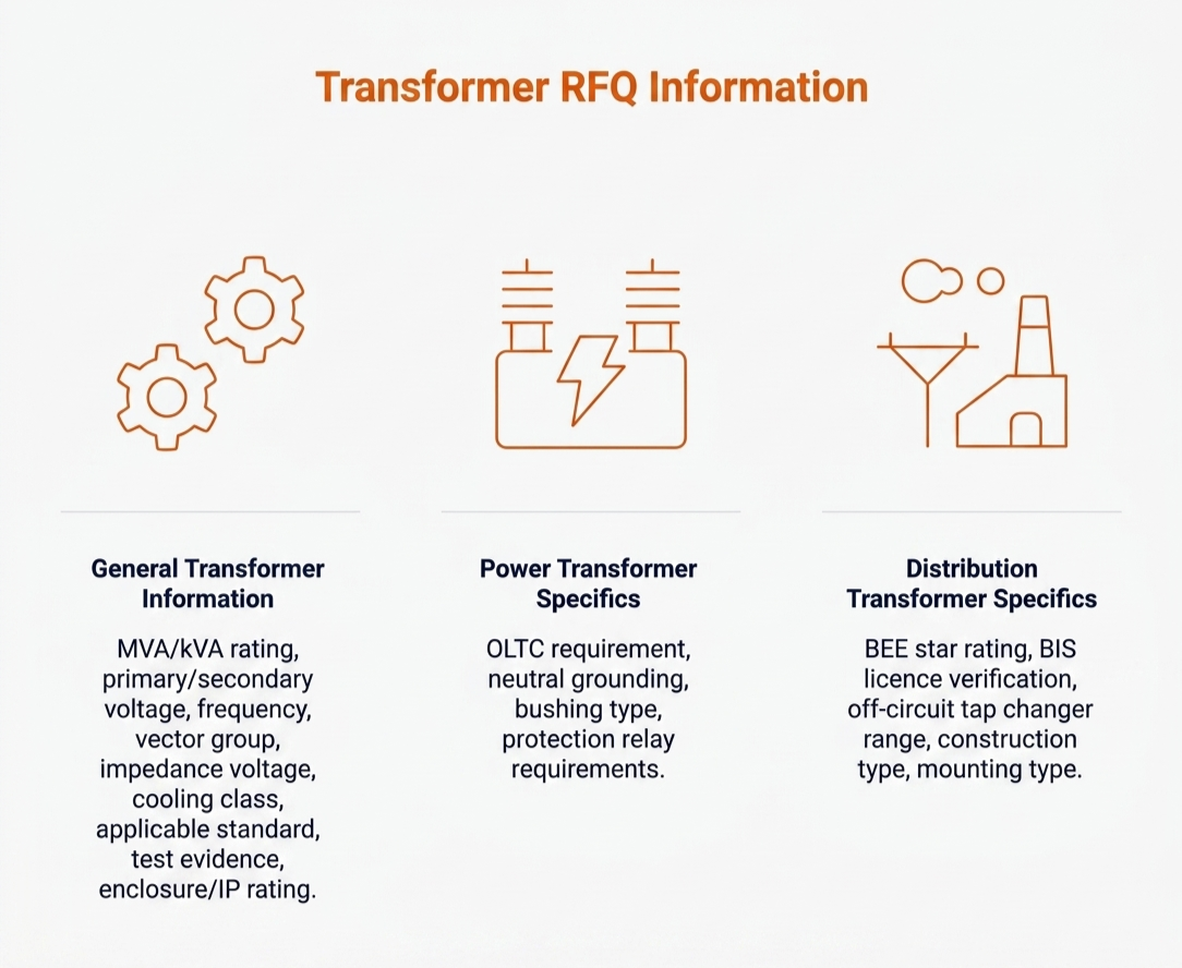
For Both Transformer Types
- MVA / kVA rating required
- Primary and secondary voltage (e.g., 33kV / 433V)
- Frequency (50 Hz standard in India)
- Vector group (e.g., Dyn11 — confirm with protection engineer)
- Impedance voltage (%) — affects fault current and voltage regulation
- Cooling class required (ONAN / ONAF / OFAF — specify site ambient temperature)
- Applicable standard: IS 2026 or IS 1180 — confirm with grid operator
- Type of test evidence required: routine test only, or full type test (CPRI)
- Enclosure / IP rating for outdoor or adverse environment installation
Additional for Power Transformers
- On-load tap changer (OLTC) requirement — tap range and number of steps
- Neutral grounding arrangement
- Bushing type and creepage distance for outdoor / polluted environment
- Protection relay and marshalling kiosk requirements
Additional for Distribution Transformers
- BEE star rating minimum (recommend 4-star or above)
- BIS licence verification required for utility supply connections
- Off-circuit tap changer range (typically ±2 × 2.5%)
- Hermetically sealed or conservator tank construction
- Mounting type: pole-mounted, pad-mounted, or indoor substation
7. Frequently Asked Questions
Not in most cases. Distribution transformers are not designed for the voltage classes, fault current levels, or continuous full-load operation characteristic of power transformer applications. The insulation levels, impulse withstand ratings, and cooling systems of distribution transformers are designed for distribution network conditions, not transmission voltages. Attempting to use a distribution transformer in a power transformer application will result in premature insulation failure or inability to obtain grid operator approval.
There is no universally fixed boundary, but in Indian practice the following conventions apply: transformers operating at 66 kV and above are always classified as power transformers. Transformers at 11 kV and 33 kV are generally distribution transformers, though large units at 33 kV (above ~10 MVA) may be classified as power transformers and specified to IS 2026 Parts 1–5 accordingly. When in doubt, specify to IS 2026 — it sets more stringent requirements and will be accepted where IS 1180 would also be acceptable.
This is a design trade-off. Distribution transformers are energised 24/7 regardless of load factor. The design prioritises minimising no-load (core) losses because these occur continuously. Accepting slightly higher load (winding) losses is acceptable because the transformer spends much of its time at partial load. Power transformers, by contrast, operate near full load most of the time, so the design prioritises minimising load losses — even if this means accepting slightly higher core losses.
Yes. KLR Transformers manufactures oil-cooled and dry-type distribution transformers, medium power transformers, and specialist units including inverter duty transformers, furnace transformers, and custom-engineered industrial units. All products are manufactured to IS 2026 and/or IS 1180 standards with test certificates. Contact our team for a specification discussion on your project.
ONAN (Oil Natural, Air Natural) is the standard cooling designation for oil-cooled transformers — heat dissipates naturally through oil convection and air cooling over the radiators, with no fans or pumps. ONAF (Oil Natural, Air Forced) adds electric fans to the radiators to increase cooling capacity — typically increasing the transformer's load capacity by 25–33% over ONAN rating. OFAF (Oil Forced, Air Forced) uses pumped oil circulation in addition to forced air fans for the highest heat dissipation. Most distribution transformers are ONAN. Power transformers above 20 MVA typically use ONAF or OFAF as continuous operation at high ratings generates heat that natural convection cannot manage alone.
Ready to Discuss Your Transformer Specification?
Whether you are specifying a power transformer for a grid substation or a distribution transformer for an industrial feeder, KLR's engineering team can help you get the specification right before the RFQ goes out — avoiding costly revision or post-installation issues.
enquiries@klrtransformers.com | [Phone] | [Website / Contact page]